Digital Filters
Filters
Change amplitude / phase of frequencies of sound
Many applications
"Tone" control, "Equalizer"
Effects, e.g. "wah"
Band limiting for antialiasing, resampling, etc
Etc etc
Common Ideal Filter Shapes
Usually 0-1 with Passband, Stopband: goal is to block some range of frequencies while leaving others alone
High Pass, Bandpass, Band Notch
Units and Normalization
Common to leave out sampling rate and gain in DSP
In time domain, samples are just numbered
In frequency domain, frequencies range from 0..1 where 1 is the Nyquist limit
Amplitude is normalized to -1..1 in time domain, 0..1 in frequency domain
We have already talked about omega, dB
- There are several dB scales floating around
Filter "Quality" Measures
The ideal low pass filter is a "brick wall":
Gain in passband is exactly 1 for all frequencies
Gain in stopband is exactly 0 for all frequencies
Transition is instantaneous (vertical) at corner frequency
Analog Filters
Made of electricity: resistors, capacitors, inductors, op-amps, etc.
Analog filters are simple, of necessity
Analog filters are kind of meh: typically use as few of them as possible when digital is available
Obvious example: anti-aliasing and DC removal "blocking" (typically a blocking capacitor)for DAC and ADC
Aside: Linear Time-Invariant Systems
Normal filter definition / requirement
Output signal is a linear function of input signal ("no distortion")
- Preserves frequencies of input waves
Output signal does not depend on input time
- Signals are notionally infinite, so this is a hard constraint
Analog filters are LTI
Digital Filters
Idea: get signal into system as close to Nyquist as possible
Do filtering mostly in software (or digital hardware)
Can build much better filters
Aside: Number Representation
Forgot to talk about this earlier: how shall we represent samples for this kind of processing?
Obvious choice: integers at sampling resolution
Can get weird for 24-bit, so promote to 32?
Math is tricky: overflow etc. Promote to next higher size?
What resolution to output? May have more or less precision than started with
Fast
Obvious choice: floating-point
Scale input to -1..1 or 0..1
32 or 64 bit? (32-bit conveniently has 24 bits of precision)
Issues of precision and resolution mostly go away (Inf and NaN).
Fast with HW support, slow otherwise especially on 8-bit hardware
Less obvious choice: "fixed-point"
Treat integer as having implicit fixed "binary point"
  .1001011000000001
  1.001011000000001
  -.001011000000001
  10010110.00000001
Fiddly, especially for languages that don't allow implementing a fixed-point type with normal arithmetic
Slightly slower than integer: must keep the decimal in the right place
Typical used on integer-only embedded systems, "DSP chips"
Strongly suggest 64-bit floating point for this course: just say no to a bunch of annoying bugs
DFT Filters
Obvious approach: Convert to frequency domain, scale the frequencies you don't want, convert back
For real-time filter output, this in principle means doing a DFT and inverse DFT at every sample position, which seems…expensive to get one sample out
Can cheat by sliding the window more than one, but you will lose time information from your signal
Also, DFT has ripple: frequencies between bin centers will be slightly lower than they should be, since they are split between two bins and the sum of gaussians there isn't quite 1
Frequency resolution can be an issue: a 128-point FFT on a 24KHz sample will produce roughly 200Hz bins, so the passband is going to be something like 400Hz, which is significant
FIR and IIR Filters
We characterize filters in terms of impulse response: what if you have an input sample consisting of a single pulse of amplitude 1 and then zeros forever?
Taking a look at the DFT sum, our DFT filter will treat an impulse anywhere in its window identically (linear time-invariant). When the pulse leaves the window, the FFT will then say 0 forever
We call this Finite Impulse Response: an impulse presented to the filter will eventually go away
A trick that we will explore is to actually use past filter outputs as well as inputs to decide the next filter output
In this case, an impulse will make it into the outputs, which means that it will be looped back into the inputs: Infinite Impulse Response
Of course, the IIR filter should reduce the amplitude of the impulse over time, else badness. Such a filter is a stable filter
FIR filters have cheap implementation (analog or digital) per unit quality, but:
Are less flexible
Are harder to design
Have lots of issues with stability, noise, numerics
Simple FIR Lowpass Filter
Let's design an FIR lowpass filter
First, some notation:
x(n)is the nth sample of input,y(n)is the nth sample of output. Amplitude of sample is assumed -1..1Filter equation:
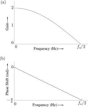
y(n) = (x(n) + x(n - 1)) / 2Why is this a low-pass filter? For higher frequencies if sample
x(n)is positive samplex(n-1)will tend to be negative, so they will tend to cancel. For lower frequencies the samplex(n)will be close tox(n-1)so they will reinforceThis filter is kind of bad: the frequency response doesn't have much of a "knee" at all
On the other hand, this filter is stupidly cheap to implement, and has very little latency: the output depends only on the current and previous samples
Wider FIR Filters
Normally, you want a much sharper knee
To get that, you typically use more of the history
For standard FIR filters, it is common to use thousands of samples of history
General FIR filter:
y(n) = (1/k) x(n-k … n) ∙ a(k … 0)So k multiplications and additions per sample
Now the cost is greater, and the latency is higher, but the quality can be very good
Where do the coefficients
acome from? More in a bit
Inversion, Reversal, Superposition
Why the obsession with lowpass? Because we can get the other kinds "for free" from the lowpass
Inversion: Negate all coefficients and add 1 to the "center" coefficient — this flips the spectrum, so high-pass
Reversal: Reverse the order of coefficients — this reverses the spectrum, so high-pass
Superposition: Average the coefficients of two equal-length filters — this gives a spectrum that is the product of the filters. If one is low-pass and the other high-pass, this is band-notch. We can then invert to get bandpass.
Convolution
A filter can be thought of as a convolution of the input signal: sum of possibly delayed weighted inputs
Convolution is probably out of scope for this course, but pretty cool
Interestingly, multiplication in the frequency domain is convolution in the time domain. This means that we can use a DFT as a convolution operator if we like
FIR "Windowing" Filters
In general, simplest low-pass filters: take a "window" of past samples, then "round off the corners" by multiplying by some symmetric transfer function
There are many window functions, each with their own slightly different properties as filters: simple things like triangular, plausible things like cosine, and weird things like Blackman, Hamming, Hanning
Note that windowing is also how we deal with edge effects of DFT: we make the signal have period equal to the DFT size by applying a window, but this also low-passes and changes the signal
FIR Chebyshev "Remez Exchange" Filters
There's a fancy mathematical trick for approximating a given desired filter shape with high accuracy for a given filter size
Involves treating filter coefficients as coefficients of a Chebyshev Polynomial, then adjusting the coefficients until maximum error is minimized
Probably not something you want to do yourself, but there are programs out there that will do it for you
IIR Filters
Can get much better response per unit computation by feeding the filter output back into the filter (?!)
In some applications, a 12th-order IIR filter can replace a 1024th-order FIR filter
Design of these filters really wants a full understanding of complex analysis, outside the scope of this course
Fortunately, many standard filter designs exist: Chebyschev, Bessel, Butterworth, Biquad, etc
Basic operation is the same as FIR, except that you have to remember some output:
y(n) = (1/(k+m)) (x(n-k … n) ∙ a(k … 0) + y(n-m-1 … n-1) ∙ a(0 … m))Always use floating point, as intermediate terms can get large / small
Really, just look up a filter design and implement it: probably too hard to "roll your own"